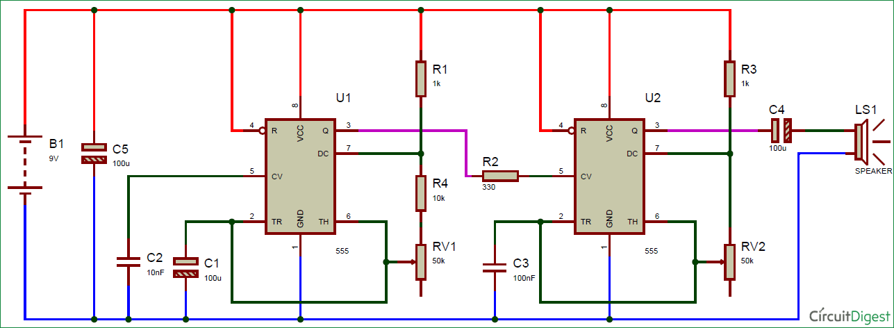
Schematic 555 Timer Circuit Diagram - KingAnupamDutta: Police Lights using 555 Timer IC - Oct 13, 2018 · this circuit produces a sound similar to the police siren.
byAdmin-
0
Schematic 555 Timer Circuit Diagram - KingAnupamDutta: Police Lights using 555 Timer IC - Oct 13, 2018 · this circuit produces a sound similar to the police siren.. You may not be able to see a clear picture of the 555 timer runs. And to calculate the component values for a given delay time, it is easier to fix the value of capacitor and calculate the resistor value. This principle is used in a comparator circuit with two inputs and an output. In this project, we will show how to build a simple led flasher circuit using a 555 timer chip. Jul 14, 2015 · we can use this property of 555 timer to create various timer circuits like 1 minute timer circuit, 5 minute timer circuit, 10 minute timer circuit, 15 minute timer circuit, etc.
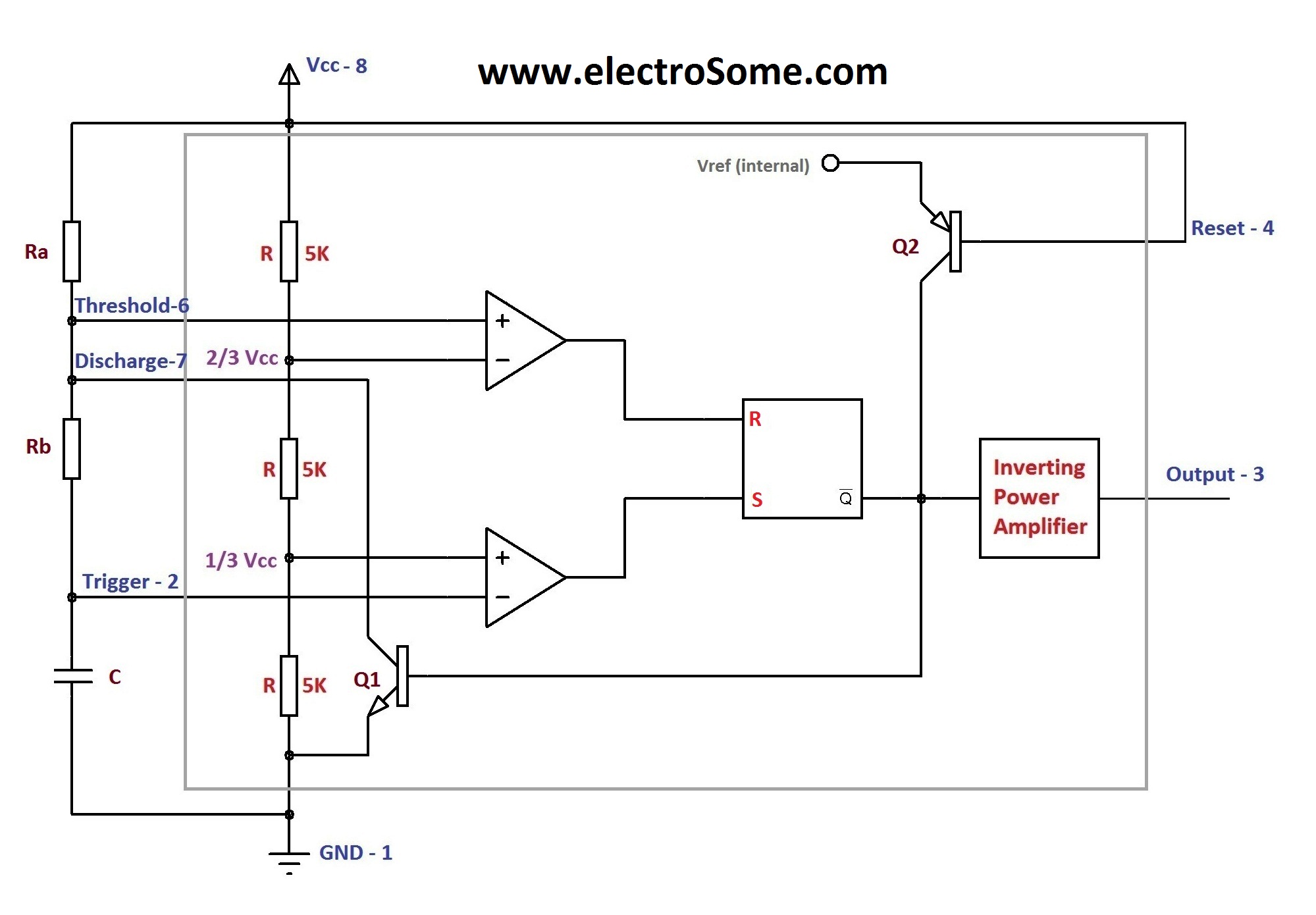
Jul 14, 2015 · we can use this property of 555 timer to create various timer circuits like 1 minute timer circuit, 5 minute timer circuit, 10 minute timer circuit, 15 minute timer circuit, etc. The block diagram of a 555 timer is shown in the above figure. T = 1.1 * (68000) * (0.000470) = 32 seconds. How does the 555 timer work. Resistive network consists of three equal resistors and acts as a voltage divider.
Astable Multivibrator using 555 Timer from electrosome.com Jump straight to an example circuit for monostable mode here. How does the 555 timer work. So, should learn it before. Monostable mode is great for creating time delays. The circuit can produce a duty cycle that is close to 50 percent but when a load is added to the output of the timer, the voltage drops across its output transistors will increase and the duty. Monostable multivibrator using 555 timer. I have used two 555 timer ics in this project and both these 555 ics act as. T = 1.1 * (68000) * (0.000470) = 32 seconds.
See in the circuit diagram is standard 555 circuit.
555 ic timer block diagram 555 ic timer block diagram. The 555 timer chip is a very versatile ic, because when connected correctly, it can it can create pulses of current at specific time intervals decided. The 555 timer ic is an integrated circuit used in a variety of timer, pulse generation and oscillator applications. Apr 15, 2020 · read next: You may not be able to see a clear picture of the 555 timer runs. Monostable mode is great for creating time delays. All we need to change the value of resistor r1 and/or capacitor c1. So, should learn it before. This principle is used in a comparator circuit with two inputs and an output. And to calculate the component values for a given delay time, it is easier to fix the value of capacitor and calculate the resistor value. In this mode an external trigger causes the 555 timer to output a pulse of an adjustable duration. In monostable mode, the duration for. Jul 14, 2015 · we can use this property of 555 timer to create various timer circuits like 1 minute timer circuit, 5 minute timer circuit, 10 minute timer circuit, 15 minute timer circuit, etc.
Resistive network consists of three equal resistors and acts as a voltage divider. Monostable mode is great for creating time delays. You may not be able to see a clear picture of the 555 timer runs. All we need to change the value of resistor r1 and/or capacitor c1. The 555 timer chip is a very versatile ic, because when connected correctly, it can it can create pulses of current at specific time intervals decided.
ding dong door bell using 555 timer circuit diagram from circuitdigest.com The circuit can produce a duty cycle that is close to 50 percent but when a load is added to the output of the timer, the voltage drops across its output transistors will increase and the duty. 555 ic timer block diagram 555 ic timer block diagram. T = 1.1 * (68000) * (0.000470) = 32 seconds. The internal block diagram and schematic of the 555 timer are highlighted with the same color across all three drawings to clarify how the chip is implemented: The 555 timer ic is an integrated circuit used in a variety of timer, pulse generation and oscillator applications. Monostable mode is great for creating time delays. How does the 555 timer work. The circuit shown in the next diagram is not an accurate method of producing a 50 percent duty cycle using 555 timers, either bipolar or cmos types.
The 555 timer chip is a very versatile ic, because when connected correctly, it can it can create pulses of current at specific time intervals decided.
We need to set 555 timer in monostable mode to build timer. And to calculate the component values for a given delay time, it is easier to fix the value of capacitor and calculate the resistor value. Jul 14, 2015 · we can use this property of 555 timer to create various timer circuits like 1 minute timer circuit, 5 minute timer circuit, 10 minute timer circuit, 15 minute timer circuit, etc. 555 ic timer block diagram 555 ic timer block diagram. How does the 555 timer work. So, should learn it before. In this mode an external trigger causes the 555 timer to output a pulse of an adjustable duration. The block diagram of a 555 timer is shown in the above figure. Between the positive supply voltage v cc and the ground gnd is a voltage divider consisting of three identical resistors, which create two reference voltages at 1 ⁄ 3 v cc and 2. Apr 15, 2020 · read next: The internal block diagram and schematic of the 555 timer are highlighted with the same color across all three drawings to clarify how the chip is implemented: Jump straight to an example circuit for monostable mode here. In this project, we will show how to build a simple led flasher circuit using a 555 timer chip.
In this mode an external trigger causes the 555 timer to output a pulse of an adjustable duration. Between the positive supply voltage v cc and the ground gnd is a voltage divider consisting of three identical resistors, which create two reference voltages at 1 ⁄ 3 v cc and 2. For example, in the circuit diagram of the fixed delay duration timer, we have used a 68k resistor and 470uf capacitor which gives us a delay time of: The 555 timer chip is a very versatile ic, because when connected correctly, it can it can create pulses of current at specific time intervals decided. You may not be able to see a clear picture of the 555 timer runs.
The History of 555 Timer IC - Story of Invention from www.circuitstoday.com Jul 14, 2015 · we can use this property of 555 timer to create various timer circuits like 1 minute timer circuit, 5 minute timer circuit, 10 minute timer circuit, 15 minute timer circuit, etc. Apr 15, 2020 · read next: All we need to change the value of resistor r1 and/or capacitor c1. The 555 timer chip is a very versatile ic, because when connected correctly, it can it can create pulses of current at specific time intervals decided. We need to set 555 timer in monostable mode to build timer. The 2 inputs, out of which one is a reference voltage (vref) is compared with each other. Jump straight to an example circuit for monostable mode here. 555 ic timer block diagram 555 ic timer block diagram.
The 555 timer ic is an integrated circuit used in a variety of timer, pulse generation and oscillator applications.
Between the positive supply voltage v cc and the ground gnd is a voltage divider consisting of three identical resistors, which create two reference voltages at 1 ⁄ 3 v cc and 2. The circuit can produce a duty cycle that is close to 50 percent but when a load is added to the output of the timer, the voltage drops across its output transistors will increase and the duty. The circuit shown in the next diagram is not an accurate method of producing a 50 percent duty cycle using 555 timers, either bipolar or cmos types. All we need to change the value of resistor r1 and/or capacitor c1. In this project, we will show how to build a simple led flasher circuit using a 555 timer chip. In monostable mode, the duration for. How does the 555 timer work. T = 1.1 * (68000) * (0.000470) = 32 seconds. We often use astable multivibrator mode. By wiring the 555 timer with resistors and capacitors in various ways, you can get it to operate in three different modes: The 2 inputs, out of which one is a reference voltage (vref) is compared with each other. Jump straight to an example circuit for monostable mode here. See in the circuit diagram is standard 555 circuit.
All we need to change the value of resistor r1 and/or capacitor c1 555 timer schematic. Resistive network consists of three equal resistors and acts as a voltage divider.